| Disclaimer:The following are my notes. As I am learning electronics, I am making my notes available. I hope they will be of benefit. However, I do not guarantee the accuracy of my work. I recommend the reader exercise critical thinking.
|
The Basics
Solar Panel
The panel I'm testing with produces 12-24 volts at 350 mAmps.
The safe charging rate of C/10 is 70 mAmps for my NiMH batteries
and 200 mAmps for my NiCD batteries.
So, 350 mAmps would be plenty for both of them. I will need to provide
something limit the current for this rate.
My lead-acid battery has a "Reserve Capacity" of "175 Minutes @ 95 AH".
I'm a little confused by what this really means. However, I feel confident
that the official AmpHour rating is at least 95 for this battery.
So, C/10 = 95/10 = 9 Amps. It would take 25 of those panels to add up to 9 Amps.
Voltage Level Detection
I needed a precise way to measure the voltage of the battery.
This was difficult to do with an unregulated input. I considered a Zener
diode, but the reverse bias saturation current made this imprecise. I chose
to use a regulator chip.
|
My first few prototypes used a 7812 regulator. This required a source of at least 14 volts. I later changed to a 7805 since some of my target battery packs would require less than 12 volts to charge.
Using a regulator means I can create a voltage reference using a
simple voltage divider made of resistors. A voltage comparator use this
reference voltage to determine whether the battery is above or below this
reference value.
I don't think the 100 Ohm resistors are necessary.
I just feel better with them there.
|
 |
Indicator LEDs
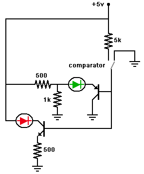
The comparator will determine when to send power to the battery.
The comparator will pull the output to ground when charged and will
provide an open circuit when charging. A 5 kOhm pull-up resistor will
provide current to the output of the comparator. When the comparator
is open, the 5 kOhm resistor will provide current to activate
the charging system.
The resistor will be grounded when the comparator is grounded. This will
also ground the associated LED indicator circuits.
|
The LEDs operate off of this same system. A PNP transistor and an NPN
transistor activate the LEDs when their bases are either grounded or
connected with the current provided by the 5 kOhm resistor.
When the comparator grounds the output,
the PNP transistor activates a Green LED, and
the NPN transistor turns off the Red LED.
When the comparator forms an open circuit,
the PNP transistor turns off
the Green LED and the NPN turns on the Red LED.
Click here for simulation.
|
 |
Power
The comparator output will turn on or off the power circuit.
The comparator circuit operates on 5 volts. The power circuit
can switch well over 12 volts. I had to use a multi-stage
turn on setup.
I also use a diode to prevent current flowing from
the battery back into the circuit.
|
My early designs utilize a PNP transistor capable of high currents.
This transistor is connected to the collector of a smaller,
low current NPN transistor.
When the comparator output is grounded, the NPN transistor prevents
current flowing through the collector. In return, the PNP transistor
(connected to the collector of the NPN transistor) will stop the
flow of current to the battery.
The 330 Ohm resistors are intended to limit the current available to the
power transistor. I don't know whether this is a good way to limit the
current while still keeping the voltage high enough. I will ponder
this later.
Click here for simulation.
|
 |
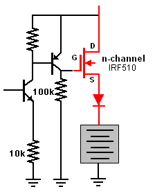
I plan to use a MOSFET later. I don't use it now, because they are easy
to damage while prototyping. RadioShack only sells N-Channel MOSFET chips.
I plan to use a staged turn on system for this MOSFET.
Here is my planned schematic.
I have not tested this yet.

Click here for simulation.
|