|
|
Offset Crankshaft
What is the Speed of a Piston
with an Offset Crankshaft?
The Question:
Some engines have an "offset" crankshaft.
An example of this can be seen in this article about the
Toyota RAV4's Engine.
So, I decided to see how an offset crankshaft changes the equations for
the speed of a piston.
Equations:
To derive an answer, I first
thought I would represent the rotation of the crank as a circle where the
center of the circle would be the axis of the crankshaft and the
circumference represents the rotation of the center of the journal. The
piston's connecting rod is then represented as a straight line. Since the
piston and the top of the piston rod travel the same vertical velocity,
the piston itself is not a factor. Since this article is about the offset
crankshaft, notice that the center of the circle representing the rotation
of the journal is offset from the vertical line which denotes the center of
the piston. Figure 1 shows this representation.
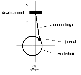 |
| Figure 1 |
Next, I derived a displacement equation to relate the following:
- The length of the piston rod
- The radius of the crankshaft
- The angle of the radius relative to a vertical line through the axis
of the crankshaft
- The offset of the axis of the crankshaft from the vertical path of the piston
This relationship was much more complicated to derive than without the offset.
The solution came by viewing the system as two triangles and finding the relationships
between them.
The goal of this derivation will be to solve for y in terms of r, d,
b and θ. The first step is to list the basic relations that are easy to spot.
Here I show the relationships for sin, cos and the Pythagorean theorem.
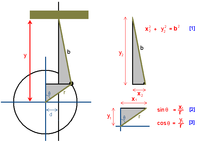 |
| Figure 2 |
|
Since I want to solve for y, I go ahead and list
the relationship for y
in terms of the sum of the heights of the two triangles.
|
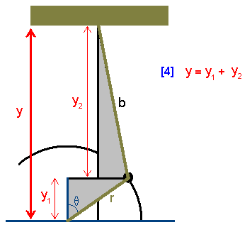 |
| Figure 3 |
|
|
The last of the geometric relationships involves the x dimensions of the two
triangles and the offset.
|
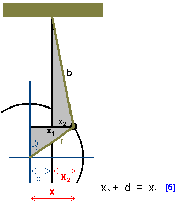 |
| Figure 4 |
|
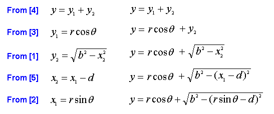
The following table summarizes the above relationships. A rewrite of the
equations is also performed in cases where solving for a specific term
will help in the goal of solving for y.
By performing substitutions of the above relationships, we can solve for
y in terms of r, d, b and θ.
On the left you will see the specific term from the above table, on the
right you will see how this term is used when substituted.
 |
| Figure 5 |
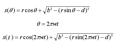
The displacement equation is then used as a function of time by substituting
a function of time for the angle. This relation of θ=2πωt is the
same as with the non-offset crankshaft. As before, I am still going on the assumption that
the rotational speed of the crank is constant when the engine is held at a constant RPM.
 |
| Figure 6 |
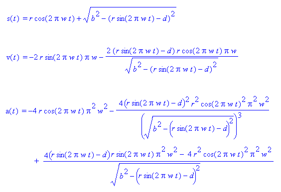
The next step is to take the first and second derivative of the displacement
equation to obtain an equation for velocity and acceleration respectively.
The derivatives of the displacement equation were derived using a
wonderful program called maple.
The graphs and equations shown here are derived from images produced with
maple.
 |
| Figure 7 |
Example:
Now let's use some numbers for these equations and generate some graphs.
I will spare you the actual equations for this example because they are ugly.
I have not been able to actually measure the radius of a crankshaft nor
the length of a piston rod. So, I am going to use a fictitious example with
the following dimensions: radius of 3.5 inches, piston connecting rod length
of 5.5 inches, RPMs of 6000 revolutions per minute. The following graphs will
show the equations without an offset (d=0) in red, and the
equations with a 1 inch offset (d=1) will be shown in blue.
The time for these graphs is measured in minutes, furthermore, all times
should be assumed as minutes unless explicitly denoted as seconds.
An Excel spreadsheet
is also provided to allow for custom dimensions to be entered.
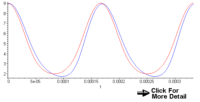
Displacement:
r=3.5 inches, b=5.5 inches, ω=6000
Blue: d=1 inch, Red: d=0 inches
 |
| Graph 1 |
We can definitely see a difference in the displacement graphs for these two scenarios.
It also appears that the graph with the one inch offset has a longer stroke. We will
compute this stroke length after we determine the time at which the velocity is zero.
However, we can
easily tell that the top-dead-center (TDC) and bottom-dead-center (BDC) occur at
different times for these two cases. Also, note that at t=0, we are not quite at
TDC actually we are 6.4° from TDC.
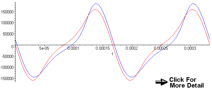
Velocity:
r=3.5 inches, b=5.5 inches, ω=6000
Blue: d=1 inch, Red: d=0 inches
 |
| Graph 2 |
The two velocity graphs definitely show a major difference. We can also observe that the
velocities are different at TDC for and BDC for the two system.
With some work, I found that the velocity is zero at about
t=0.000002953412 and t=0.000097222225 minutes. We can also see that the piston
reaches a higher velocity on the up-stroke than on the down-stroke.
| With an offset of 1 inch |
| t (minutes) |
Angle(degrees) |
v(t) (inches/minute) |
s(t) (inches) |
| 0.000002953412 |
6.379 |
0.0019 |
8.94427191 |
| 0.000097222225 |
30.000 |
0.0058 |
1.73205081 |
|
Since the velocity is zero at both the top (TDC) and the bottom (BDC) of the stroke,
we can now find the length of the stroke. By taking the difference
in the two displacements for the time of TDC and BDC, we come up
with about 7.2 inches for the stroke: s(0.000002953412) - s(0.000097222225) = 7.21222110.
The example without the offset had a stroke length of 7.00 inches.
So, the stroke is indeed longer with the offset crankshaft in
this case.
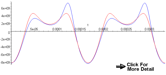
Acceleration:
r=3.5 inches, b=5.5 inches, ω=6000
Blue: d=1 inch, Red: d=0 inches
 |
| Graph 3 |
Sorry, but I am not quite done with this page.
|
|